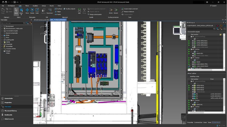
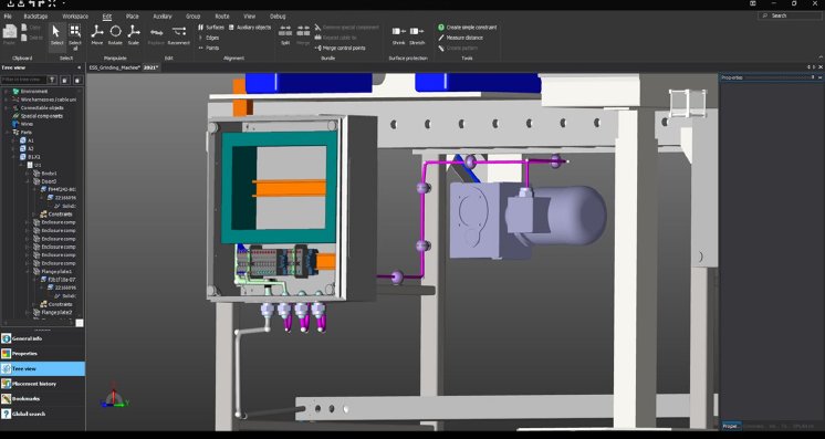
Finding the right cables, planning, designing and plotting their routing for assembly? Until now, this has been a very laborious process for electrical design engineers in machine building. Solutions provider Eplan has now expanded its 3D software Eplan Harness proD to cover the practical requirements for machine field cabling. What’s long been standard in the mechanical environment is now moving into electrical engineering – the digital twin of the cabling. Depicted in Eplan Harness proD, this unique product data source is usable in manufacturing, assembly and even service and maintenance – by combing electrical and mechanical engineering. The common device database for the Eplan systems ensures an unambiguous source for all the data. One clear advantage in practice is that every designer can work in their own way, each with their own view of the machine in question: mechanical engineering continues working with assemblies and electrical engineering with functions.
System-supported designing and routing of cabling pathways
The process for cable planning is incredibly simple. The electrical engineer plans the necessary cables in the schematics using Eplan Electric P8. She then, almost in passing, defines the required devices for the cabling designs in Eplan Harness proD. This where the decisive advantage in the process become clear: the common device databank for all the Eplan systems, a consistent, uniform source of data. After that, she links the electrotechnical project with Harness proD and imports the 3D geometry from mechanical engineering into the cabling tool. With all this information, the external equipment is placed into the 3D environment, cabling pathways are defined with system support, and the cables are then routed. Once all devices and cables have been introduced, the designer receives a digital twin of all the cabling. This twin now has a dual effect: it can be provided to the mechanical design team as a 3D assembly, or be transferred to the electrical engineering team with the added cabling information.
Prototyping – virtual is better than physical
What only first becomes apparent after the physical prototype is built (when using tradition working methods) becomes visible much earlier using this more integrative process. Changes, for instance when creating the prototype, can be handled with just a few mouse clicks in the program. An actual physical prototype from manufacturing isn’t required at all. The digital twin is the medium for collaboration in engineering or even for starting constructive dialogues with clients – whether it’s during the specification phase, the development phase for design reviews, or even for marketing purposes. Here’s an overview of just some of the advantages:
- Complete Eplan project (the single source of truth)
- Transferring the digital twin to mechanical engineering
- Complete bills of materials, including cable lengths for electrical engineering
- Cable assembly drawings for special cables that must be produced to spec
- 3D HTML viewer for assembling and servicing
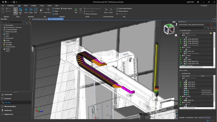
With the current 2023 version, users now have access to all devices in the electrical engineering category as part of device management in the Eplan Platform. Data from motors, connectors, cables and so on are available in full. This central overview of devices facilitates managing the master data. If a control cabinet of some sort (from Eplan Pro Panel) is integrated into the machine, all the components and their connection information can also be easily transferred. This forms the exact starting point for field cabling. Another example is planning cable routing. Even now, in Version 2023, cable ducts, energy chains and cable trays can also be used for cable routing. No matter if the mechanical engineer is the person who designs them, the electrical engineer always knows precisely if the cables will fit through the intended pathways and the exact lengths required.
Eplan at the Hannover Messe
17 to 21 April 2023
Hall 11, Stand E06


