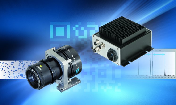
Especially when machine vision has to be integrated in an existing automation system, this is often more easily done with a smart camera solution than with a PC based vision system. Smart camera solutions are smaller, they generally generate less heat, and therefore can be a better choice if localized pass/fail decision making or process control are requested.
A modular Smart Line Scan Camera System basing on ARM-Platforms
Most smart line scan systems incorporate the processor into the camera housing. While this all-in-one solution has its advantages, it tends to produce rather large camera housings. But often space is limited and it is then more convenient to have a small camera combined with a small separate computing unit. This is also more flexible, because the camera can be replaced independently of the computing unit.
This prompted Schäfter+Kirchhoff to develop the Smart Control Box which connects to any of the monochrome series USB 3.0 line scan cameras via a rugged industrial-grade interface. Together they perform as an autonomous measuring unit directly attached to the machine or in close contact to the object. They are measuring widths, diameters, distances, edge or peak positions and many more values. Good-bad decisions are made according to adjustable tolerances. Measurement results and decisions are transmitted either via fieldbus or analog signal to a higher-level control unit like a PLC or a process control computer.
The heart of the Smart Control Box is a high-performing ARM 8-core 64-bit processor well suited for signal and image processing. The rugged design of the box with IP65 protection simplifies integration in rough environments.
The box is configured via its LAN connection in client-server mode. From then on it can operate stand-alone or further in client-server mode, where system commands and requests are sent from a client computer via Ethernet and the measurement results are returned from the system accordingly. To facilitate the setup and adjustment of the sensor the server can provide complete line signals to the client in real time. This is very helpful to check the correct alignment of the camera to the measurement object and to the illumination used.
In client-server mode, the maximum distance between client and server is 100 meters. Up to 8 Smart line scan camera systems can be handled and controlled by a single client.
In stand-alone mode, output from the smart line scan system is also possible via Profibus, RS232, digital I/O or two analog outputs with 16 bit resolution.
The line scan camera can be operated in free-run mode, where it takes line scans at a user-defined fixed frequency. In case of a constant movement velocity, this is suffiencent.
For varying velocities the motion unit has to be equipped with an encoder that sends trigger signals to the camera. There are separate inputs for line synchronization and frame synchronization. An internal programmable frequency divider in the camera reduces the trigger frequency if necessary.
Smart line scan camera systems are predestined for one-dimensional measurement tasks, where they determine the position and width of an object, or the position of an edge or a signal peak. This results in a continuous stream of measuring results that can be sent directly to a programmable logic controller (PLC) or a process controlling computer.
The use of a smart line scan camera systems should especially be considered when machine vision has to be integrated in an existing application. A modular system consisting of a line scan camera and the Smart Control Box presented in this article has advantages regarding space requirements and offers greater flexibility compared to an all-in-one solution. Smart line scan camera systems are predestined for continuous one-dimensional measurements, providing a continuous stream of measuring results.

