An analysis of the data will reveal that stability and long-term behavior are significantly improved by the new sensor cell, which now consists of 6 moving masses. The new adapted ASIC features additional innovations.
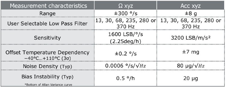
The first outstanding feature is its improved zero-point stability (bias instability) compared with its predecessor, the SCHA63T, whose stability of 1.2°/h was already pretty impressive, but this has now been halved to 0.5°/h. This performance measures up to that of high-quality IMUs or FOGs, whose prices can quickly reach into the four-digit range.
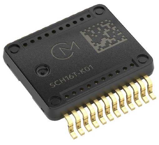
The redesigned sensor cell has facilitated the leap from a larger “pre-molded” product to a smaller 24-pin SOIC housing with a smaller internal mass. To provide further stability, the area of the sensor unit was turned downwards.
A further innovation as a result of the redesign of the ASIC is the connection of the sensor to a processor unit. Eight different filter settings, from 13 Hz to up to 370 Hz cut-off, are available. The dynamic ranges for gyro (1.5 g to 8 g, head room up to 25 g) and acceleration (52°/s up to 300°/s) can be selected via registers.
Previously, there were two individual ASICs, each with its own SPI in the 6DoF sensor; now, there is only a single unit. For this purpose, the interface originating from the automotive sector, SafeSPI v2.0, is used with 20- or 16-bit words with a simultaneous CRC check.
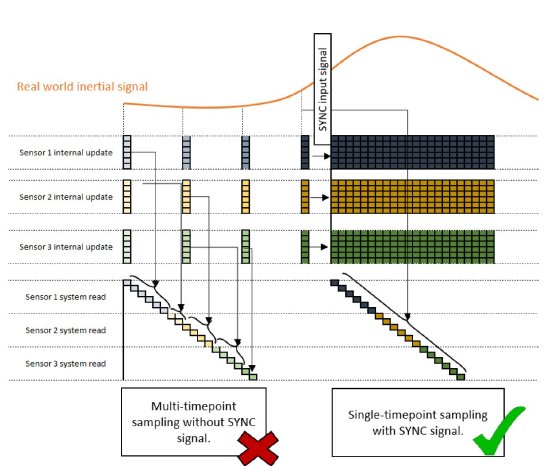
For applications where multiple sensor units are connected via a BUS, reading the data without using an individual MISO line can take longer than the available update time of the internal registers. In certain cases, this can result in a significant discrepancy due to sampling of various time points of the individual sensors. A SYNC pin was integrated for such cases, meaning that multiple sensors are addressable.
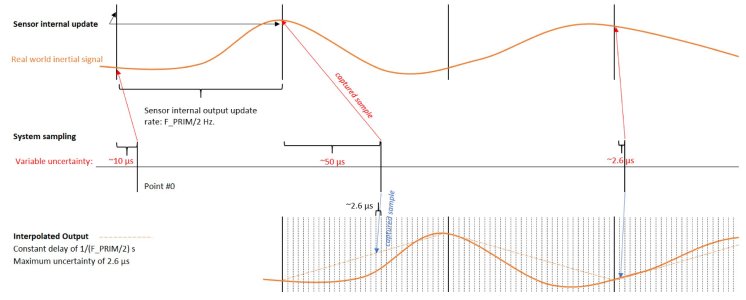
If the MCU clock of the host system is used as a reference, the value of the data counter can be combined with the value of the frequency counter in order to calculate the precise time stamp of a measurement. This combination is used if integration processes for sensor data are performed and the time uncertainty, or “data jitter”, of the interpolated data does not meet the system accuracy requirements.
With regard to the sensor data, the SCH16T offers various data output options. To improve the data jitter described above, the data for gyro and acceleration can be output in interpolated form. If the resulting quantity of data needs to be reduced, the “decimation” option can help. For dynamic systems, it is important that all data that arises or is available be used to record data from all axes simultaneously, for example. However, since the natural output data rate at the nominal primary frequency is 11.8 kHz, this can result in overloading of the MCU. The purpose of the “decimation” function is therefore to reduce the internal update rate to give the host system enough time to read each individual “sample”. A third option is interpolated data output, which is well suited for short-term dynamic ranges of up to 25 g.
Various registers perform the tasks of a self-test function (STC) by conducting a continuous self-test of the gyro, accelerometer and start-up routine by writing a “0”. The start-up time is max. 250 ms with a stable power supply.
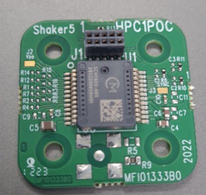
There are two different PCBs for analyzing the sensor. One with just the sensor on a PCB (SCH16T-PCB) for a shaker. The second version (APNM-SCH16T) can be used for a shaker and is suitable for surface mounting. In addition to the sensor, this second PCB includes a powerful 2xFPU 32-bit processor, which, combined with licensable firmware (algorithms, CAN) from Nordic Inertial, serves as an evaluation kit and acts as an open IMU.
