During energy production in fossil fuelfired power plants, various types of fuel are burned inside a combustion chamber. The released heat is conducted to the tube bundle inside the surrounding boiler shell; steam produced inside the tube bundle is used to power steam turbine generators for electricity production.
The boiler erection operations can be divided into three main parts:
- Making available the appropriate pipes with matching dimensions, made of the requested material, corresponding to the specified quality level, shipped at the desired date;
- Prefabrication work such as cutting, joining and bending of the pipes in the workshop;
- Final boiler assembly with the prefabricated parts on site.
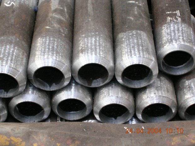
Pipes available on the market are generally of fixed lengths, which depend on production methods, transport limitations etc.
During prefabrication, the pipes are welded together to get appropriate lengths for the preassembled units.
These are shipped to the site where they are used to construct the boiler.
Prefabrication: joining by welding parts or bending of a welded tube
The prefabrication can be organised in two different ways, which results in different structures concerning the production line and the required equipment.
The first prefabrication technique consists of welding several pipes together (depending on the length of the delivered pipes for example two or three sections); the final shape of the preassembled unit is arrived at by joining them with bends (Fig. 1).
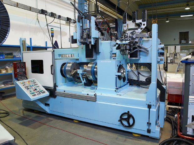
This prefabrication technique requires a welding machine for the joining of the tubes at the beginning of the production line. At this stage of operation the workpieces are still rotationally symmetrical, so the welds are carried out usually on rotating tubes with the torch at a fixed position. On the commonly implemented welding lathe the tubes are clamped, centred and rotated at the desired travel speed to carry out the weld. The proper welding operation is performed by means of the welding torch which remains in a fixed position.
The welded tubes are taken out of the welding lathe and, after testing of the welds and an in some cases necessary heat treatment, they are assembled using corresponding bends and form pieces. A significant number of welds have to be realised, either manually, or by means of orbital welding. The production time of these preassembled units can be considerably influenced by the number of welding machines and staff available to execute this work.
In the second method of prefabrication, many pipes are welded together. The final length corresponds to the total length of the preassembled unit, which can be up to 100 metres. Several bending operations are then carried out to transform the preassembled unit to its final shape.
This type of prefabrication requires virtually all welds to be carried out by the welding lathe or tube welder at the beginning of the assembly line. The total production time of each preassembled unit is influenced strongly by the capacity of this machine.
Due to the importance of these straight tube welders their design has been continuously improved and adapted to the specific needs of production. With the increase in efficiency of power plants, higher service temperatures became necessary and new heatresistant materials had to be developed, making welding operations more and more delicate.
Creep rupture strength diagram: suitability of materials can be estimated
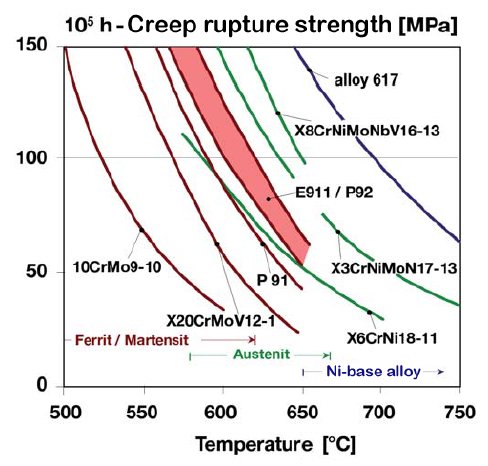
The suitability of materials under high mechanical stress and elevated temperatures can be evaluated by means of a creep rupture strength diagram (Fig. 2). Above the service temperature in degrees Celsius (abscissa) the mechanical tension (Mega Pascal) which can be tolerated by the workpiece during 1 x 10⁵ h is indicated (ordinate). By agreement, its value for power plants is set to 100 MPa.
Improved materials - increased service temperature and efficiency
Since 1950, the high temperature steel X 20 Cr Mo V 12 1 (X20) with 12 % chromium has been used successfully in Germany and many other countries for fossil fuel fired power plants of 150 MW in size. However, manufacturing and welding of this material demands great care and has to be carried out thoroughly; it has never been added to the ASME code (American Society of Mechanical Engineers).
In 1980 the martensitic steel P91 with 9 % chromium was introduced in the USA. Due to its increased creep rupture properties it allowed a rise in service temperature from 540 °C to 600 °C. This steel is figuring on the ASTMspecification A335 (American Society for Testing and Materials) and on the ASME Boiler & Pressure Vessel Code, in the DIN standard it is specified as X 10 Cr Mo V Nb 9 1 under the material no. 1.4903.
The development of E911 and P92 martensitic chromium steels allowed a further rise in service temperatures and efficiency (Fig. 2). These materials can also be used for repair and replacement of older boiler components; the lower required service temperature leading to considerably decreased wall thicknesses of the parts. In addition to material savings, easier installation and less weld metal to be melted, the reduced wall thickness brings down the mechanical stress which results in longer life expectancy of the components.
Further enhanced service temperatures will only be possible if austenitic steels or nickelbased alloys are used.
Controlled heat input preserves material properties
The increased creep rupture strength of these types of high temperature steel is based on specifically conditioned microstructure properties, which if possible, should not be altered by the welding process. Changes to the microstructure and brittleness caused by a too rapid cooling of the workpiece can be avoided by preheating; overheating and modifications of the micro structure due to excessive welding temperature are excluded by limited interpass temperatures; and internal stress of the parts caused by welding can be removed by an adequate post weld heat treatment. Preheating and heat treatments must be carried out by resistance or inductive heating, operating with naked flames does not provide the required precise control of the process and provokes partial overheating and hence is not permitted.
Conditions to be respected when welding heatresistant or high temperature steel for steam boiler purposes are listed in Table 1.
Tube welders must be designed to clamp tubes with diameters from 22 millimetres to approximately 76 millimetres. If finned pipes, i.e. pipes which are equipped with baffleplates, with diameters of more than 100 millimetres need to be welded, special clamping units become necessary.
Particular torch position reduces arc time
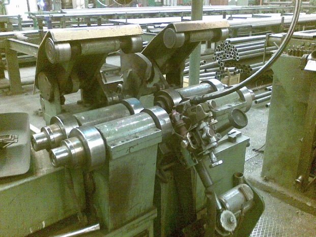
Straight tube welders are commonly equipped for MIG/MAG or TIGwelding. Despite its lower performance, TIGwelding is preferred in Europe because of its increased weld quality. Due to improved construction of the machine, it has been possible to drastically reduce the arc time of the TIG welding process. The welding torch has been fixed at the seven o'clock position, as seen at an old VKWmachine (Fig. 3), so pipes with a wall thickness of 5 mm (and in some cases even 7 mm) can be buttwelded in a single pass.
On some straight tube welders the pipes were joined by friction welding, but this method did not gain acceptance for a long time. However, the excellent concentricity precision of these machines was later used to position the tubes, even though the joining was realised by orbital TIGwelding.
Retrofit: rugged machines with modern welding equipment
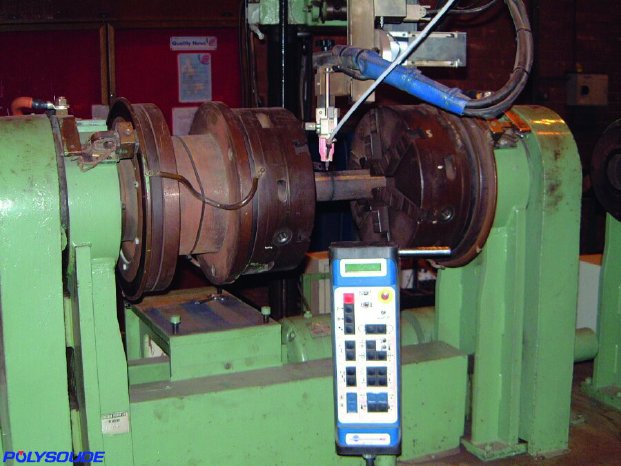
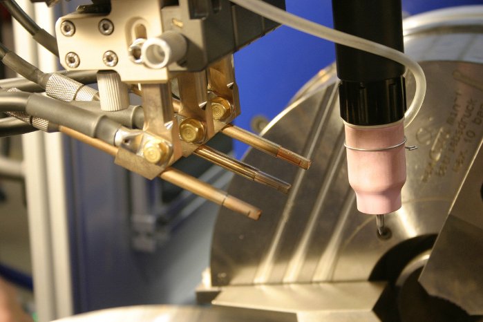
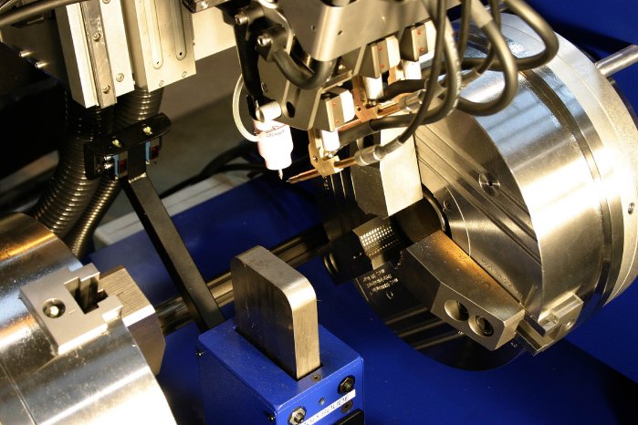
The design of the straight tube welders had been adapted to the harsh operating conditions of the workshop, featuring rigid frame construction and heavyduty mechanical components. For this reason it can become economical to overhaul such machines (Retrofit) and add modern welding equipment. An older straight tube welder with recently installed stateoftheart TIGwelding components is shown in Fig. 4. The torch with the reddish ceramic nozzle at its end, and the protruding tungsten electrode, is fixed in the twelve o'clock position. In front of it, the hose for the filler wire with a nozzle and the positioning device are situated.
The microprocessorbased control of the weld cycle is then integrated into the power source; the necessary commands are stored as a program in its memory. To obtain a perfect synchronisation between the movement and the welding operation, the rotation of the pipes is controlled by the power source as well. The welding is started via the remote control pendant; the cycle is carried out automatically without any further intervention from the operator. If necessary, however, weld parameters can be corrected directly during welding.
Virtually defectfree joints by TIG welding
Unlike MIG/MAGwelding, where current intensity, arc length and wire feeding speed are interdependent, TIG welding allows adjustment of the wire feeding independently from the arc length and current. The ignition of the arc, the premelting at the beginning of the weld, and a perfect downslope at the end are carried out without filler wire, so defects in the weld can be excluded in these zones.
Prefabrication method requires significant investment
A production line using the second prefabrication method, where a very long pipe is welded together at the beginning, requires significant investment. A workshop of sufficient length and large surface area must be available to allow the bending operations, as well as adequate bending machines and heat treatment equipment. Costeffective production can only be achieved with efficient workload of the production line, requiring its quick and easy adaptation to various work orders.
The most recent types of straight tube welders are designed to offer highest flexibility; improved automation and integration into the production chain to guarantee reliable and reproducible welding results.
Straight tube welder allows choice of multiple welding processes
These machines generally offer a choice between MIG/MAG and TIG cold wire or hot wire welding. The TIG hot wire process allows a reduction in the welding time, so it matches approximately the time required for MIG/MAGwelding. The pipe end preparation (Vpreparation) is also identical for both processes (Fig. 5). However, problems at the beginning and the end of the weld can be solved more successfully with TIGwelding, allowing a zero defect result level to be obtained.
The welding equipment for MIG/MAG and for TIGwelding are each mounted on a mobile carriage each; one carriage always occupies one of the parking positions (Fig. 6), while the second one is fixed in the working position. The carriages are moved manually; collisions are avoided by pneumatic locking. To change between MIG/MAG and TIG welding, the required carriage must be moved into the working position, no mechanical modifications or changes in the electrical or pneumatic connections are required.
Software-controlled wire management
Once the welding process has been selected, MIG/MAG for example, the required carriage is fixed in its working position. For MIG/MAG welding, the machine offers the choice between two types of wire. Two complete welding units including two separate wire spools, two wire feeding devices and two torches are installed on the carriage. The desired torch can be indicated in the weld program and is positioned automatically.
The TIGprocess can be carried out with three different types of filler wire. Also controlled by the program, the nozzle which is guiding the selected wire is moved to its position in front of the TIGtorch (Fig. 7).
Tilted torch positions modify welding characteristics
The general adjustments of all torches are carried out manually, tilted positions allow welding with the torch directed towards the finished part of the weld or towards the part of the weld still to be made; to reach an additional offset position the torches can be displaced on a slide.
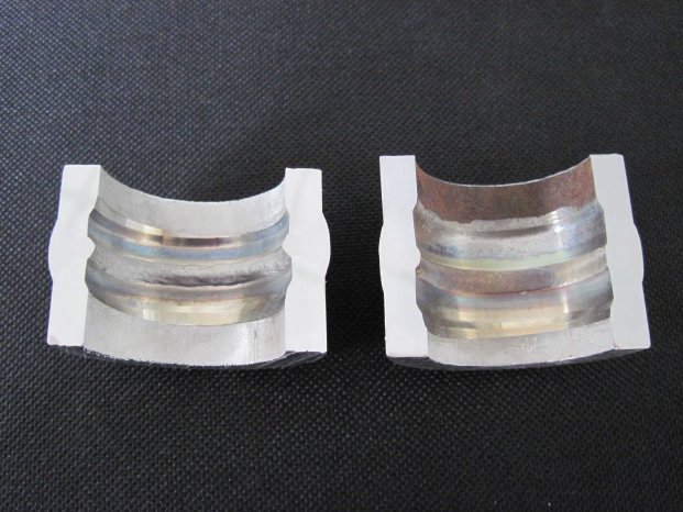
For the acceptance procedure of a modern straight tube welder, test welds on different pipes for boiler construction have been carried out. Characteristic welding parameters are listed in Table 2; the sectioned joints are shown in Fig. 8.
Weld acceptance procedures according to relevant technical regulations
It is the client's responsibility to specify the mode of acceptance of the welds based on the relevant technical regulations such as the ASMEstandard IX, the ASTMcode or the DIN standards. Depending on the regulations, visual inspections as well as destructive and nondestructive test methods have to be applied.
In Table 3, an extract of the Chinese Steam Boiler Safety Technology Supervisory Regulations JB/T 2636-94 including the acceptance criteria for the evaluation of a destructive test of the welds is given. In this case the surface of the weld is ground to the level of the tube O.D. and a notch is machined in the middle of the weld seam. The joint is then broken at the notch, so any weld defects become visible and can be classified corresponding to the listed criteria.
Well-arranged control elements encourage operator
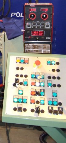
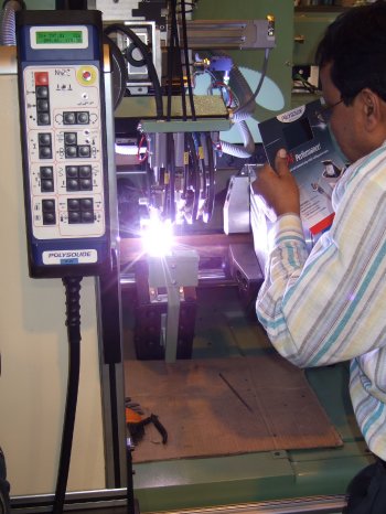
In general, a straight tube welder is equipped for three kinds of operation. The tube handling, i.e. the supply and removal of the workpieces and their positioning, is carried out via a control panel (Fig. 9). A console installed at the top allows to adjust parameters for MIG/MAG welding and to control the process. A remote control pendant (Fig. 12) is used for TIGwelding and, for example, to modify the torch position or welding speed during a welding operation.
For the handling of the pipes to be welded, a control panel is installed (Fig. 9). The end of the first pipe is moved through the hollow shaft of one chuck to rest against a retractable stop (Fig. 10) and then clamped in this position. The second pipe is also clamped in a specified position against the retractable stop, and once the stop has been retracted, it is shifted towards the end of the first tube. The torch is moved automatically until its distance to the workpiece corresponds to the programmed value, in the case of TIGwelding a programcontrolled centring of the tungsten electrode in the middle of the weld gap can be carried out.
Safety-relevant parameters are continuously monitored
The microprocessorbased sequencer controls the entire straight tube welder and is integrated into the power source of the TIGwelding equipment. All safetyrelevant parameters are monitored; for example all welding operations are blocked if the carriages or torches are not fixed in their appropriate positions or the welding gas supply is interrupted. A continuous data exchange is maintained with subsequent machines, during a weld cycle no tubes can be loaded or unloaded and if an Xray test is executed, all pipe movements remain blocked.
An Xray test can be carried out after each weld. If a serious defect is detected, the weld can be completely cut off and replaced by a new one.
Weld parameter corrections are always possible
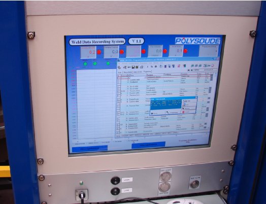
The weld cycles for the different workpieces are programmed on a PC with the easytounderstand Windows© based welding software POW (Fig. 11) and transferred to the memory of the power source. All essential weld parameters such as current intensity, arc length, travel speed and wire feed speed as well as up and downslope can be precisely reproduced in each weld cycle. The commands to setup the equipment can be given via the remote control pendant; necessary parameter corrections can be carried out online during welding (Fig. 12).
Conclusion
During the construction of boilers for fossil fuelfired power plants a significant quantity of the required pipes are welded at the prefabrication stage in the workshop. The production time of the preassembled pipes is strongly influenced by the capacity of the weld lathe installed at the beginning of the production line. Various designs of these straight tube welders have been developed. Increased flexibility can be achieved if a modern type is used, while MIG/MAG as well as TIG cold wire and hot wire welding can be selected without manual conversion of the machine. The TIG hot wire process guarantees high productivity, a zero defect result weld level can be achieved. The machine allows the selection between three different types of filler wire, in case of MIG/MAG welding process two different wire types can be chosen. The change between the different wires is controlled by the program and carried out without any intervention by the operator. With this type of straight tube welder, work orders with dissimilar tubes and materials can be treated without mechanical modifications to the machine.
Older tube welders in existing production lines should be checked for modernizing possibilities. Reconditioning and installation of stateoftheart welding equipment (Retrofit) can help to improve productivity and reliability even with a modest budget.
Dr.-Ing. Jürgen Krüger, Lippstadt, Germany
