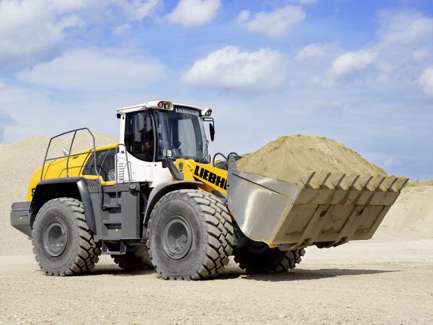
As you drive over the large bridge, you can already see the 220,000-square-metre factory. There they are, what men dream of: wheel loaders of all sizes, from five to 34 tonnes, with buckets that can load up to 14 m3 at a time. And immediately on the right is the entrance area with huge mounds of sand, stone and earth where customers can try out the earth-moving equipment and make standard comparative tests. Who wouldn't want to get behind the wheel and start driving right away? Well another time perhaps, because today is all about how the wheel loaders are manufactured, or more precisely about the machining of the front and rear steel components. Since commissioning of the new SHW PowerSpeed 6 with twin columns in April 2013, productivity in this area has increased by up to 40%. Let's take a closer look.
Flexible production line for a wide range of products
At the Liebherr factory, founded in 1960, wheel loaders have been built since 1985. Initially, cranes were built as well but since 1996 the production has focused exclusively on so-called flexible earthmoving equipment with the characteristic articulated steering and rear steering axle as well as oscillating frame articulation and centre-pivot axle. 1000 people work at the factory in Austria where 3500 to 4500 vehicles can be produced every year. What is special about Liebherr is the wide variety of almost 20 different types of wheel loader, which can be tailored exactly to the customer's requirements and application, "in principle, just as you would order a car or a commercial vehicle today, choosing exactly the options you require," says George Ganitzer, Head of Production. Liebherr's particular expertise, when it comes to the products they manufacture, lies in the mechanical production operations such as robotic welding, painting, assembly, testing and even sheet-metal working. The new machining centre is part of the on-going optimisation of the production lines to increase flexibility.
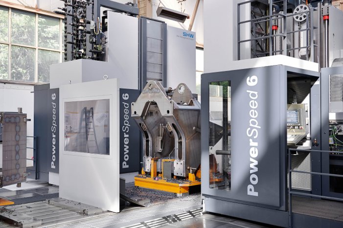
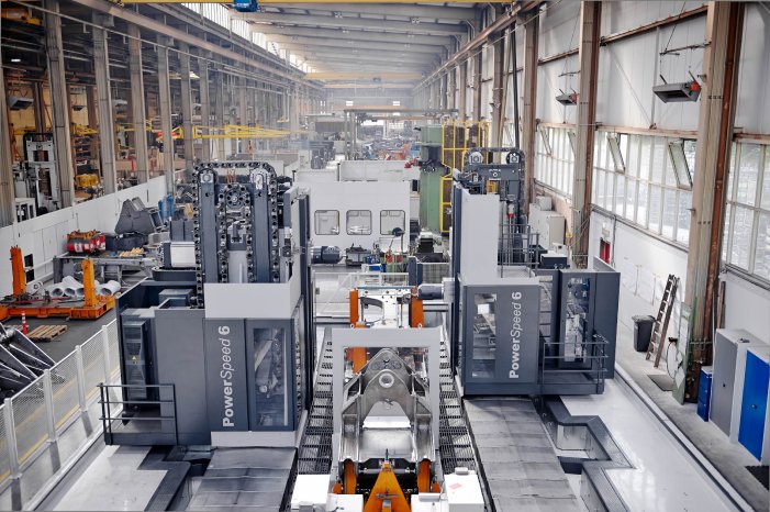
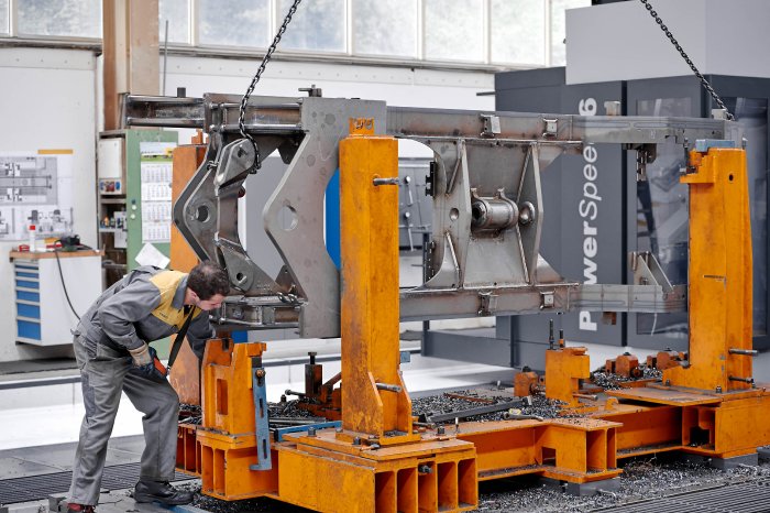
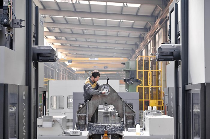
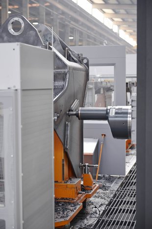
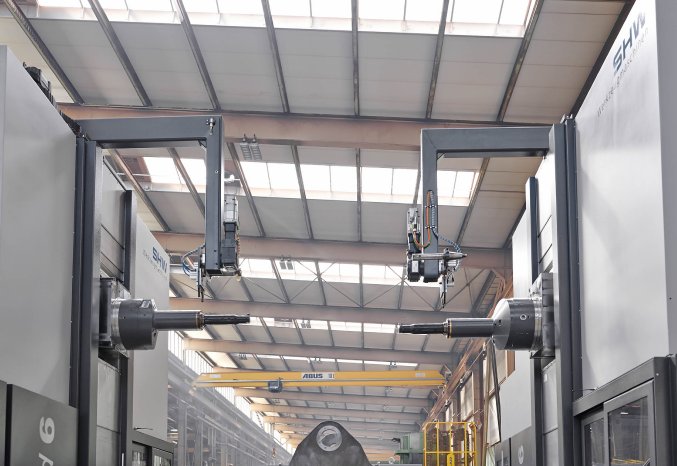
To manufacture the front and rear subassemblies, Liebherr uses a flexible manufacturing line with zero-point clamping systems and a high degree of automation, in order to ensure the shortest possible production times. To achieve this, the Austrians have installed an SHW PowerSpeed 6 machine with two travelling columns. Strictly speaking, these are two machines that communicate with each other," points out Danny Basic, Head of Marketing at SHW WM. Thus the welded and prefabricated components can be machined in parallel in a single setup. "By simultaneous milling, drilling and finish boring of sheet metal up to 120 mm thick on both sides, now just one machine is needed where previously two were required," says Raimund Promegger, an experienced foreman in the Liebherr production shop. Travelling at speeds of 30,000 mm/min along the 12,000 mm long axes, the twin columns can quickly reach any position on the workpieces which may be up to 4500 mm long.
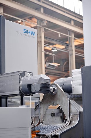
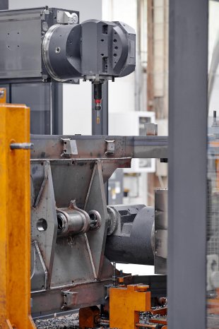
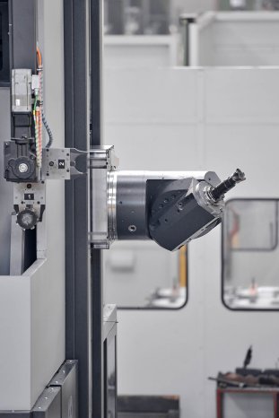
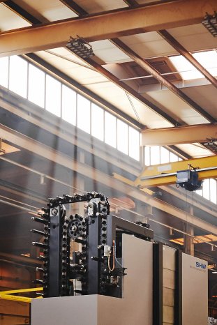
Vertically the headstock travels at up to 3100 mm in the Y-direction and horizontally up to 1500 mm in the Z-direction. At the heart of the SHW machine tools for over 50 years now is the compact and powerful universal milling head in orthogonal design. With the versatile milling head, over 216,000 positions on the workpiece can be reached quickly and accurately thanks to the 180° swivel range of the A-axis and 360° continuous rotation of the C-axis, as provided on all models with head change system. The compact head swivels fully automatically to every desired position. "This provides exactly the flexibility we need," says Ganitzer.
Machining in parallel saves about an hour
Workpieces weighing up to 30 tons can be machined on the CNC rotary table which is 2000 mm in diameter. While the front and rear components of the current vehicles do not weigh that much, leaving their options open for such potential components is an integral part of Liebherr Bischofshofen's flexibility strategy. In addition there is also an 8000 x 2000 mm clamping plate. Each of the two halves of the wheel loader is mounted on a purpose-built workpiece carrier with a zero-point clamping system so they can be moved from the set-up area to the machining position. Each of the two columns, of welded-steel design and equipped with anti-friction compact guides and liquid-cooled feed drives so they can accelerate and move quickly, has its own tool magazine with up to 150 tools. Likewise each column has a fully automated head change system (HCS) which, depending on the machining task in hand, selects the universal or the eccentric horizontal milling head.
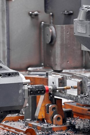
Thus, very well equipped, the two heads can get to work. Finished contours are milled and the provided openings finish bored to H7 tolerances. Reaming and thread tapping follow. On the front component, for example, pivotal mountings for cylinders, steering bearings and lifting gear require machining. On the rear component, mountings are required for auxiliary equipment such as engine bearings, hydraulics, cooling and transmission. By machining both sides of a component in parallel, it is possible to finish all the operations required on one machine in a single setup after just one-and-a-half hours. Ganitzer is delighted with the increased productivity: "It used to take about two-and-a-half hours and machining of the components was divided between two machines."
DynamicDrive® for fast and accurate machining
This is made possible among other things by the DynamicDrive® system, developed and patented by SHW Werkzeugmaschinen, which makes it possible to cover large travel distances with projecting milling heads at high speeds without significant loss of rigidity or precision. This clever solution ensures that, when the headstock is being moved, the machining axis always remains parallel to the machining table and thus to the surface of the workpiece being machined. "DynamicDrive® compensates in real-time for any gravitational pull downwards on the headstock as well as for any deflection upwards of the milling head, due to the resistance of the workpiece during machining," says Martin Rathgeb, Technical Head of SHW WM. Thus differing weight ratios, due to the different weights of the milling heads, can be balanced out. The trick here is the division of the headstock slide into two parts which are then connected to each other via a radial bearing mounted on a hydro-pneumatic oil film, permitting them to rotate. Furthermore the whole carriage "hangs" on a hydraulic counter-weight so as to be able to adjust it with great precision. The data required for this is received from its own real-time measuring and control system, thus permitting dynamic correction based on the actual conditions.
Exploiting the power of the software
The powerful Siemens 840D SL control system offers great scope to the experts in Bischofshofen. "We like to get everything we can out of the control system to optimise the process," Ganitzer says in conclusion. So that the dreams of the men outside the production shop at the "big sandpit" can still to be fulfilled in the future.
