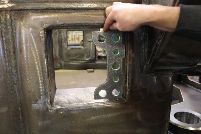
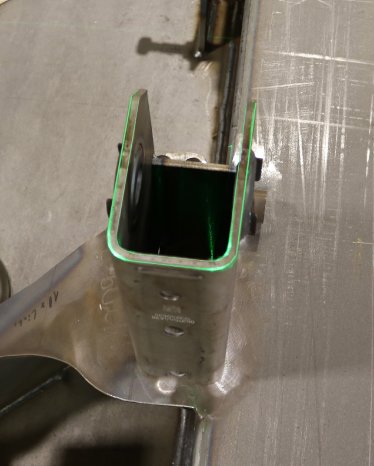
- for aligning welding components
- for positioning clamping devices on different work tables
- for projecting cutting lines and contours for the layout of metal parts
- for workpiece display for drilling and milling work
- for quick set-up of steel trusses
- for positioning cutting, bending and forming lines
- for pattern generation for the automation of repetitive work
We are reporting here on a company that manufactures vehicles for a payload range between 20 t and 10,000 t and delivers them worldwide. The first laser systems from SL Laser GmbH have been in use at the Memmingen plant since 2006. Before the laser projectors were used, the components were positioned in the traditional way with the help of plans and measuring aids such as tape measures and folding rules. Among other things, this led to long cycle times and the usual measuring errors.
Today, the laser projectors are used at two workstations. At the first, two laser projectors are permanently mounted above a welding table. At the second workstation, a mobile laser is used on a movable trolley, which is used flexibly for larger components. Outlines of components are projected. A PC is used for both workstations, which loads and projects the prepared projection files using the installed SL 3D software.
The projection process
First, the laser must be calibrated. At the fixed laser station, this is done using calibration points that are inserted into the hole grid of the welding table. At the mobile laser station, the laser calibrates itself using calibration points that are attached directly to the component. After calibration, the projector projects the first contour of the add-on part. The sequence is determined by work preparation when the projection file is created or is changed directly at the workstation if necessary. As soon as the projected laser beam is congruent with the component edge, the add-on part is correctly positioned. Remote control is used to switch from Layer to Layer.
To assist the operator, large monitors can display the current work steps or components in enlarged form. The SL3D software allows the screen to be split. In addition to the current contour of the add-on parts, additional work instructions for the worker can be displayed in image or text form, for example.
According to the user, the use of the laser saves 30% to 40% of the working time per axle carrier frame, as a lot of time is needed for measuring without the projection.
Thanks to the laser display, measuring errors and the risk of components being forgotten in the process are eliminated.
The work preparation department creates the projection files in advance
The relevant employee uploads the CAD drawing and then defines the lines that are to be projected. The contour of the add-on parts is usually divided into individual layers, which are later switched through by remote control. Labels or position numbers can also be projected. The target points for the orientation of the laser are defined on the table's perforated grid system or, in the case of the mobile laser station, directly on the component.
The introduction of the system by SL Laser
For new customers, SL-Laser prepares a projection file together with the customer for an initial demonstration of the laser projectors. The work preparation department recognizes and learns the procedure and can organize itself accordingly. The 3D data from the component in STEP or IGES format serves as the basis. As soon as the customer puts the system into operation himself after the first test runs, SL Laser is available to provide advice by telephone or via remote connection.


